(Team 4) – Muhammad Hussain – mhus9984
It has been a grueling few weeks. We are looking towards presenting our first installation at the Sydneham Skatepark. But before we can proceed we had to finalize some of the matters that were unclear. Some of the questions were; Should we be using sound? What kind of sensors would we use? What type of display are we using? To this point we had already decided on the space (after careful inspection of the other options for our installation) where we would be doing the installation. The space that we had chosen was the Skate Bench near the green patch towards the parking side of the Skatepark.
In the week eight’s presentation and evaluation we proposed that all the visual design would be either displayed on LED Matrix, Television screen or a Projector. It was also proposed that sound would be used to provide a wholesome experience for the viewers and the skaters. The tutors were skeptical about the idea of LED Matrix being used on the Skate bench directly. Some of the issues that they raised were power consumption by the LED Matrix, some issues were safety related and some, space related. But they liked our idea that a Television screen be used for display purposes.
These were our first iterations of the concept presented in the presentation;
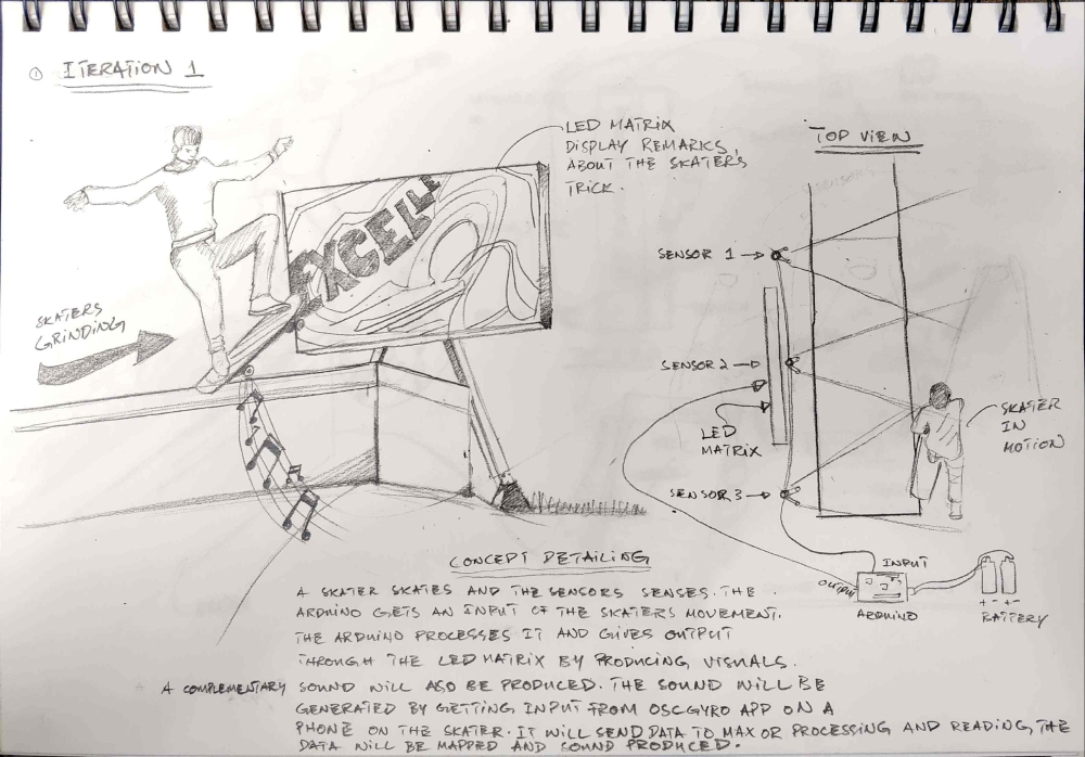
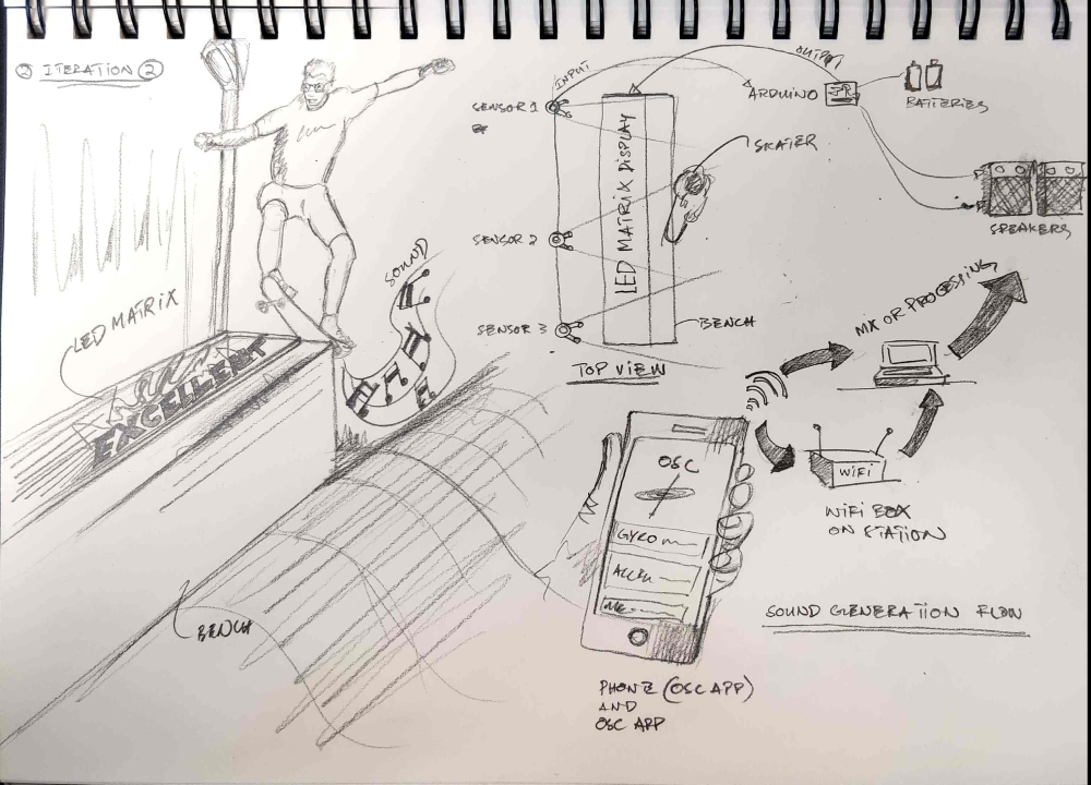
We planned in the next meeting to gather up our material and devise the installation. We decided to use three major components after careful research. One was the LED Matrix, the TV screen and LED Strips. We divided the work three-ways. Since these were three components each group member got one component. Our goal was to make them work together. The proposal about sound was eliminated. And I got the part of using an LED matrix and making it work. My job was to make the LED Matrix work. The LED Matrix was for inviting the skater into the experience by displaying graphics and complimentary words.
I researched LED Matrix and there were a number of different types. There were RGB Matrix which was colored. And there were single color LED Matrix. We chose single color because that was apt for our purposes. The LED Matrix’s purpose was to invite the user into boarding our experience. After we finalized the skate bench among all the other skate benches. We found a proper place which was best for engaging and calling upon the user, to get them interested in the installation. The LED Matrix would invite and make the skaters and the spectators aware that beyond this line is an installation, and they will be a part of that installation when they will enter it. Furthermore, the skater will engage and get into grinding on the skate bench and experience the design fully and the spectators will just see the feedback after the skater has engaged with the installation.
As I have understood through my research the LED dot matrix is a 2 dimensional array of patterned LEDs that produce displays of letters, words and images. In the modern day many devices use displays that have LEDs e.g. Mobiles, TVs and Tablets. The LED Matrices that we will use for this installation is an LED matrix that is actually low resolution. The size is 32 x 16 cm. Concurrently the number of LEDs in the columns are 16 and the number of LEDs in the rows are 32. The size was decided judging by the purpose of this part of the installation plus the space that it was going to be installed in.
The LED matrix that we will use is a 32 x 16 red dot matrix that we purchased from Jaycar Electronics. This Matrix needs to be programmed through Arduino IDE. It has a complex circuit that needs to be carefully connected. This device runs on 5V. It can be connected directly to the Arduino Uno/Red board for power but it would be very unstable and the LEDs will be extremely dim. We need external power for the LED dot Matrix to realize its full potential. The Jaycar electronics sold me the LED Matrix but I had no idea how to connect it initially. After doing a thorough research on the circuitry and a bit of trial and error, I found out that without cutting any wires I can easily power the LED Matrix by purchasing a 5V adapter that converts the regular voltage to the required electricity needs for the LED matrix. So after a systematic run through of different techniques for powering the LED Matrix I found a suitable solution.
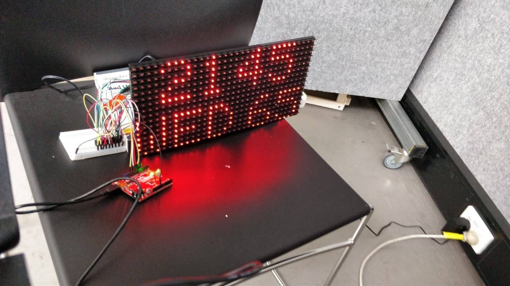
This picture shows the connection of the LED Matrix with Arduino and getting power from the regular electricity socket. We have decided to use extension cords to get power through the power points during the Pilot SK.8. This adapter will be extremely feasible for the purposes of getting power from the regular power points. I will be explaining the circuitry, coding and box making process for the LED Matrix and how I made it work in my next blog post. There were many aspects of this component that needed testing and trial and error to reach the point of displaying graphics and words. This process required a number of back and forth steps that in the end rendered fruitful results.
