(Xiangbin Cai: Circuit building and Prototype Package. Guang Feng: Arduino & Processing Coding. Siyu Zeng: System Testing)
Week 1-Week5
Xiangbin Cai’s work:
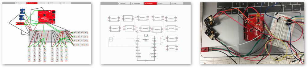
In the process of building the first circuit of our design, according to the discussion with teammates and the requirement of design concept, I develop and build a circuit which contains 1 IMU sensor input, 2 PIR sensor input and 12 LED strips output. And I also add 3 resistor(330 Ω) to each analog port to protect the circuit. In addition, the whole circuit is controlled by one Arduino module and all the component are powered by the Power port(5V). Also, at this stage, all the connection is supported by Breadboard.

At the beginning, we planed to create 2 LED matrix through 12 LED strips in the middle area, section 37.
Week6 – Week10
Xiangbin Cai’s work:
Subject: circuit rebuilding and connection refinement
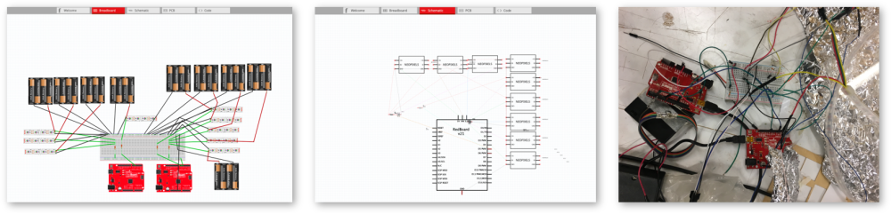
After several testing of our prototype and having a consultation with one of our tutor, especially the meeting with site manager-Annie, we are permitted to give up using PIR sensor because of the low sensitivity of this sensor. Even though only use one PIR sensor to detect motion, the feedback was still unsatisfying. So we pay more attention to improve the usage of IMU device. So I rebuild a whole new circuit with 2 Arduino module, at this design, we use 9 LED strips in total.
In this circuit, each LED strips will be powered by each battery enclosure(5V) and we choose 2 cellphone(IMU app – GyrOSC) as data input which are connected with Processing through WIFI.
More specifically, in terms of lighting effects and interactivity, we decide to use analog port A5, A6 from one Arduino to control 8 LED strips flashing and analog port A5 from another Arduino to control 1 LED strips. So, to protect the circuit, I design insert 3 resistor(330 Ω each) to connect every analog port I need, but also have one more resistor to share the voltage of 8 LED strips.
Guang Feng’s work:
In this period of time, the connection between the mobile app and the processing, the processing and the connection of the Arduino are mainly solved.
Overview
The first version, the implemented features:

The user shakes the mobile phone, data is transmitted to Processing, limits the acceleration on the X and Y axes between 0 and 50. According to this value, the PIN on the Arduino connected to the processing is assigned by Firmata.
About LED effects
0~30 PIN0 is HIGH and the light is white.
30~40 PIN1 is HIGH for the pink light.
40~50 PIN 2 is HIGH for the red light.
To achieve the effect of controlling the light.
I started with the library of FastLed to achieve the effect of the water light, but the effect of the light is controlled by a sine function. I found this function in the library, but I can’t modify the period. I can’t just let it run for half a cycle, from left to right. right.
So I switched to NeoPixel. https://www.tweaking4all.com/hardware/arduino/adruino-led-strip-effects/ and selected Fade in and Out, Meteor Rain and Fire as the display.
The delay function in Effect affects the speed of change, and it takes a lot of time to try to solve this problem, and finally it is not successful.
About Sensor
Firstly, I tested PIR sensor while high speed moving, the result shows the PIR sensor is not sensitive enough even when I changed every data.
Karen recommended “GyrOSC” as a remote IMU sensor.
Set the IP address and port correctly, and connect with Hotspot of computer.
About Arduino and Processing Connection
At first, I tried to use serial to transmit data, but it is very hard to transfer data from processing to Arduino.
First attempt to use Firmata, we referred StandardFirmata to achieve the function “Arduino reads data from Processing”. This file includes 20+ functions and beyond 800 lines, this is why it takes much time to upload.
Processing is used to receive data from phone. According to https://github.com/crecord/gyroOscBridge, I successfully read the IMU data of iPhone on Processing.
Week 11
Guang Feng’s work:
In this period of time, add two LED strip in a heart, and change the triggering conditions,and add an Arduino, add a sound while running pulse effect.
Overview
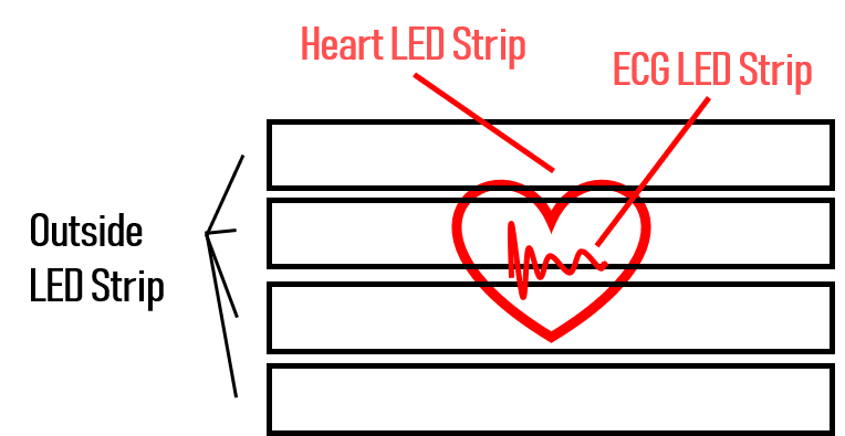
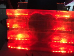
Add a heart-shaped acrylic plate with a hollowed-out ECG. There are LED strips around the heart and the ECG (Heart LED and ECG LED). When the user shakes the phone, 4 LED strips outside the heart(Outside LED strips) and the ECG LED will change, they shared same effect. The outline of the heart is another effect (Pulse effect). As the times of mobile phone shakes increases, the heart rate gradually accelerates. Finally, Outside LED strips will execute the modified Fire function(from 2 side), and the effect in mind is the very fast heartbeat, and it is called the final effect.
About Arduino
Initially, all the LED strips were controlled with one Arduino. However, the Arduino could only run one LED strip effect in a period of time, so the final result was changed to use two Arduino controls.
Processing controls a main Arduino through the Firmata, the Arduino is controlling Outside LED strips, and then connects the digital port of the main Arduino to the digital PIN of another Arduino via the jumper. The other Arduino uses the digital signal to make the corresponding effect. However, this method has a problem, and Arduino returns an error when uploading frequently.
About Processing
- Set the Arduino loop that controls the outline of the heart LEDs to execute a pulse function whenever the specific PIN is HIGH. There is Processing to change the value of its PIN. This is done to facilitate the addition of a sound. Whenever the pulse function is to be transmitted, a pulse sound is played first, which synchronizes the sound with the pulse effect.
- I spent a lot of time adjusting the synchronization of the sound and the lighting effect. Since the function that can’t play the sound in the processing is followed by delay(), the first time is to use the millis() function to control the time of digitalWrite in Processing, but the problem is, as the heart beats faster, the interval between playing sounds and lighting effects will also change. Try to use variables to control the interval, but because it is too complicated, the actual effect is not good, and finally gave up. The last thought is to add a delay (300) function to the Arduino code each time you receive a signal to perform the lighting effect. Add a delay (200) function when changing quickly.
- The action judgment condition has also been modified. As long as any acceleration in the X or Y or Z direction exceeds 1 value, it is regarded as an action. After the distance from the last action is more than 1000ms, the action will cause the counter +1. If there is no action for more than a certain period of time, the counter returns to zero.
- Deleted functions in Arduino which are not used in Firmata, add a global variety which control green and blue value, it could be changed in AnalogWriteCallBack(), it means the color value can be changed by processing.
Week 12
Xiangbin Cai’s work:
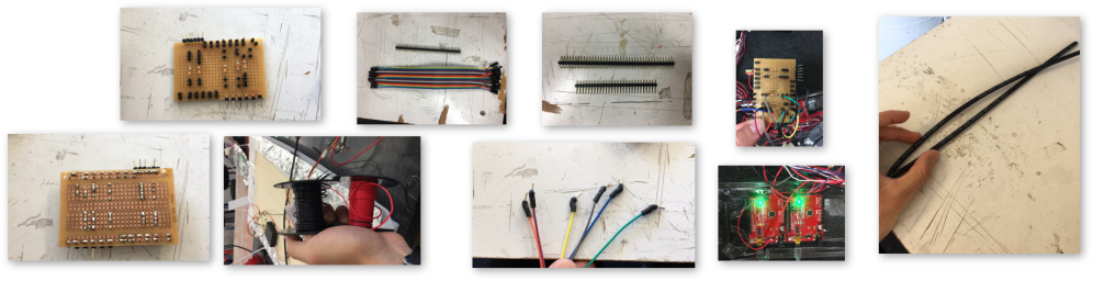
Subject: final system circuit refinement and utilization of multipurpose PC board
After the peer-user testing in lab, and the second site-installation test on site, there are some problems toward the existing circuit design with the whole connection of project.
1.The copper sheet on PC board falls off easily
2.The wires connected to LED strips and batteries are nor long enough which affects the installation of our project
3.The traditional jumper wires are not connected so tight between Arduino board and PC board.
In order to deal with these problems, after discussion with teammates, I soldered a variety of terminal pin to PC board for providing more alternatives. In addition, I create a new type of wires by Connecting one terminal to Male/Female Jumper wires, which can enhance the connection between Arduino board and PC board. At the same time, I utilize external black or red wires to extend the length of the wire. For safety consideration, I use hot melt pipe to enhance the connection of re-soldering wires. I also prepare some backup wires for the event.
Guang Feng’s work:
Overview
In this period of time, add two LED strip in a heart, change the triggering conditions,add an Arduino, and add a sound while running pulse effect.
Now we have two users!
- In order to increase the interactivity, I added another mobile phone. In fact, I replaced the PIR sensor in the original concept and added a new OSC object in the processing code and replaced it with a new port. This processing can simultaneously acquire data from two mobile phones.
- In order to make the line clearer, I added a new Arduino class object to the processing, so that the two Arduinos are directly controlled by the processing.
- There are now two counters that record the actions of two users. The previous Final Effect is now set to a trigger condition where both counters are greater than a specific value.
- The LED strips outside the 4 hearts and the ECG LED strip inside the heart are controlled by an Arduino. Heart LED are controlled by another Arduino.
- Design and make a heart-shape object, put a speaker in the object and connect with Bluetooth.

Siyu Zeng’s work
In week 12, I did technical testing.
For the users, I designed 5 test cases.
Since the codes are related with the time of the IMU movement, the first case was to let skaters kept still and audiences shaked heart box once. The data results showed that beatcounter=0;vesseelcounter=1; accelVessel.x(y/z)=0.5; accelHeart.x(y/z)=0. The light result I expected was that the light of electrocardiogram kept flowing while 7 light boxes showed same color however the lighs were gradient from red to purple to blue. By the way, there were should be no heart color. The actual result I got was as same as what I imagined.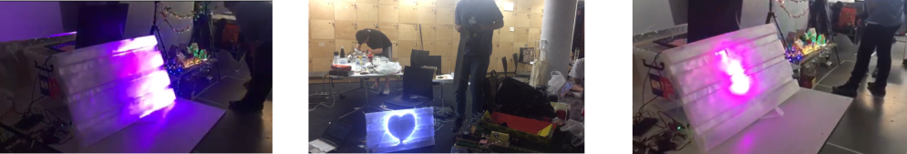
The second test case I created was to let skater kept moving and audience kept still. The data results showed that beatcounter=1;vesseelcounter=0; accelVessel.x(y/z)=0; accelHeart.x(y/z)=0.5; The light result I expected was that only showing the light of the heart shape. The actual result I got was as same as what I imagined.
The third test case I created was to let skater kept still and audience kept still. The data results showed that beatcounter=0;vesseelcounter=0; accelVessel.x(y/z)=0; accelHeart.x(y/z)=0; The light result I expected was no light. However, the light of the heart still showed green. In the beginning, I thought it was a code bug. But later I checked it with my teammates, we found that one of heart shape cables was broken. After testing, we fixed this problem and soldered cable firmly again.

The forth test case I created was to let skaters did trikes twice and audience shaked heart box twice. The data results showed that beatcounter=2;vesseelcounter=2; accelVessel.x(y/z)=0.7; accelHeart.x(y/z)=1; The light result I expected was that the light of the heart was red. And the light of electrocardiogram kept flowing while 7 light boxes showed same color however the lighs were gradient from red to purple to blue. The actual result I got was as same as what I imagined.


The fifth test case I created was to let skater did trikes five times and audience shaked heart box more than twice. The data results showed that beatcounter=5;vesseelcounter=4; accelVessel.x(y/z)=1; accelHeart.x(y/z)=2; The light result I expected was the light of heart is purple. And the light of electrocardiogram kept flowing while 7 light boxes showed same color. However the lighs were gradient from red to purple to blue. The actual result I got was as same as what I imagined.
The final test case I created was to let skater did trikes eight times and audience shaked heart box several times. The data results showed that beatcounter=8;vesseelcounter=12; accelVessel.x(y/z)=1; accelHeart.x(y/z)=4; The light result I expected was the light of the heart is red. And no electrocardiogram light while 7 light boxes showed same color. However the lighs were gradient from red to yellow. The actual result I got was as same as what I imagined.
